resistance entre chanel 1 et 2 oscilloscope | oscilloscope repeating signals resistance entre chanel 1 et 2 oscilloscope All the pictures used in this article, minus the block diagrams, were captured on an actual oscilloscope. The process of capturing these pictures involved fidgeting with various settings in order to get the desired signal to properly display. However, this was . See more On the Fenikss casino website, you can play slot machines, as well as place bets on sports events. The casino welcomes its new customers with an welcome bonus! Overall, the casino is rated 4.6/5. Experts recommend this casino to players who want to gamble from their mobile phone.
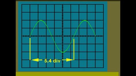
0 · oscilloscope repeating signals
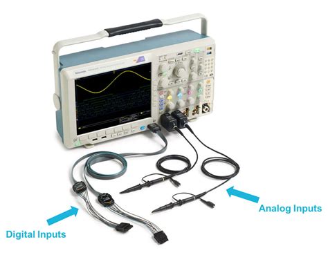
1 · oscilloscope input channels
2 · oscilloscope infinite persistence mode
3 · oscilloscope frequency chart
4 · oscilloscope circuit
5 · oscilloscope channel 2 trace
6 · oscilloscope channel 1 square
7 · channel 1 oscilloscope generator
Feline immunodeficiency virus (FIV) vaccine efficacy and FIV neutralizing antibodies. Efficacy and potential prophylactic mechanism (s) of prototype and commercial FIV vaccines. James K. Coleman, b,a Ruiyu Pu, b,a Marcus M. Martin, b Ezra N. Noon-Song, b Raphael Zwijnenberg, c and Janet K. Yamamoto b,d,*
Learn how to use the oscilloscope, frequently referred to in the trade as a scope, which is an essential diagnostic tool used in any . See moreWith modern scopes, the display is simply a rectangular area with an X-Y grid pattern. This grid pattern can be an actual overlay, or a . See moreAll the pictures used in this article, minus the block diagrams, were captured on an actual oscilloscope. The process of capturing these pictures involved fidgeting with various settings in order to get the desired signal to properly display. However, this was . See moreThere are two basic kinds of scopes – analog and digital. The general description presented in the previous section applies to both kinds. . See more
Learn how to set up and operate an oscilloscope including grounding, controlling, calibrating, probing, and measuring with this guide from Tektronix engineering experts.An oscilloscope is for looking at the behavior of a circuit, so the first step is to build a circuit and hook up probes. You'll be building the circuit on the right. Some things to know: Good values .To do this, simply insert a low value resistor in the supply line to a given circuit, and hook up two scope probes, channel 1 and channel 2, for example, as shown in figure 10. Then, setup the scope to show the difference, using the ch1 – ch2 math function, between these two signals.Learn how to set up and operate an oscilloscope including grounding, controlling, calibrating, probing, and measuring with this guide from Tektronix engineering experts.
An oscilloscope is for looking at the behavior of a circuit, so the first step is to build a circuit and hook up probes. You'll be building the circuit on the right. Some things to know: Good values for the resistor and capacitor are 430K Ohm and 0.002uF, respectively.In order to measure the voltage across element 3, we need the difference between channels 1 and 2. Channel 1 v. Channel 2 display (xy or A-B mode) • Sometimes you don’t need to see each waveform as it changes with time, but you want to know how . It is important to note that oscilloscopes only measure voltages not currents or resistances however it is possible to convert quantities such as current, strain, acceleration, pressure and so forth into voltages that can then be used by the oscilloscope.
The input circuit of a general-purpose os-cilloscope consists typically of a 1M re-sistor in parallel with a small capacitance, perhaps 30pF 1. Let’s consider the effect of this 1M resistance in parallel with 20pF of capaci-tance (the input impedance of the Syscomp DSO-101 oscilloscope).I already have a 4 channel oscilloscope but it's quite old and I might have some money soon to upgrade with. The price for a 4 channel is almost 2-3x that of a 2 channel, but is the cost justified by the increased utility?Calculate the magnitude of the impedance, angle of the impedance, series resistance, and capacitance of the unknown capacitor. Compare the magnitude of the impedance, angle of the impedance, series resistance, and capacitance of the two capacitors.
The input impedance of an oscilloscope is a complex quantity which can be represented by a resistance in parallel with a capacitance between the scope input terminal and the ground. The impedance is thus frequency dependent.The usual solution is to use a “10x” passive scope probe which has a resistance of 9MΩ in parallel with an adjustable capacitor of about 5pF. When the capacitor is adjusted to be 1/9th of the capacitance of the scope input plus probe lead, the probe will .To do this, simply insert a low value resistor in the supply line to a given circuit, and hook up two scope probes, channel 1 and channel 2, for example, as shown in figure 10. Then, setup the scope to show the difference, using the ch1 – ch2 math function, between these two signals.Learn how to set up and operate an oscilloscope including grounding, controlling, calibrating, probing, and measuring with this guide from Tektronix engineering experts.

oscilloscope repeating signals
An oscilloscope is for looking at the behavior of a circuit, so the first step is to build a circuit and hook up probes. You'll be building the circuit on the right. Some things to know: Good values for the resistor and capacitor are 430K Ohm and 0.002uF, respectively.In order to measure the voltage across element 3, we need the difference between channels 1 and 2. Channel 1 v. Channel 2 display (xy or A-B mode) • Sometimes you don’t need to see each waveform as it changes with time, but you want to know how . It is important to note that oscilloscopes only measure voltages not currents or resistances however it is possible to convert quantities such as current, strain, acceleration, pressure and so forth into voltages that can then be used by the oscilloscope.The input circuit of a general-purpose os-cilloscope consists typically of a 1M re-sistor in parallel with a small capacitance, perhaps 30pF 1. Let’s consider the effect of this 1M resistance in parallel with 20pF of capaci-tance (the input impedance of the Syscomp DSO-101 oscilloscope).
I already have a 4 channel oscilloscope but it's quite old and I might have some money soon to upgrade with. The price for a 4 channel is almost 2-3x that of a 2 channel, but is the cost justified by the increased utility?
Calculate the magnitude of the impedance, angle of the impedance, series resistance, and capacitance of the unknown capacitor. Compare the magnitude of the impedance, angle of the impedance, series resistance, and capacitance of the two capacitors.
The input impedance of an oscilloscope is a complex quantity which can be represented by a resistance in parallel with a capacitance between the scope input terminal and the ground. The impedance is thus frequency dependent.


giày gucci nam real

oscilloscope input channels
Radio SWH džeza klubs ar Dayme Arocena (Kuba) Riga, Spīķeri Concert Hall. € 35 – 50. Buy tickets. 20. Jun. 20:00. Rīgas Festivāls.
resistance entre chanel 1 et 2 oscilloscope|oscilloscope repeating signals


